Electric motors are also called motors (commonly known […]
Electric motors are also called motors (commonly known as motors) and are represented by the letter "M" in the circuit (the old standard uses "D"). Its main function is to generate driving torque as a power source for electrical appliances or small machinery.
The motors introduced in this article are low-power motors used in household appliances or electronic products, so-called micro motors.
(1) Types of electric motors
There are many types of motors.
1. According to the working power source classification According to the different working power of the motor, it can be divided into DC motor and AC motor. Among them, AC motors are also divided into single-phase motors and three-phase motors.
2. Classified by structure and working principle Motors can be divided into asynchronous motors and synchronous motors according to their structure and working principles.
Synchronous motors can also be divided into permanent magnet synchronous motors, reluctance synchronous motors and hysteresis motors.
Asynchronous motors can be divided into induction motors and AC commutator motors. Induction motors are divided into three-phase asynchronous motors, single-phase asynchronous motors and shaded-pole asynchronous motors. AC commutator motors are divided into single-phase series motors, AC and DC motors and repulsion motors.
According to the structure and working principle, DC motors can be divided into brushless DC motors and brushed DC motors. Brushed DC motors can be divided into permanent magnet DC motors and electromagnetic DC motors. Electromagnetic DC motors are divided into series-excited DC motors, shunt-excited DC motors, separately-excited DC motors and compound-excited DC motors. Permanent magnet DC motors are further divided into rare earth permanent magnet DC motors, ferrite permanent magnet DC motors and Alnico permanent magnet DC motors.
3. Classification according to starting and operating modes Motors can be divided into capacitor starter motors, capacitor motors, capacitor starter motors and split-phase motors according to their starting and running modes.
4. Classification by use Motors can be divided into drive motors and control motors according to their uses.
Driving motors are divided into electric tools (including drilling, polishing, polishing, slotting, cutting, reaming, etc.) motors, household appliances (including washing machines, electric fans, refrigerators, air conditioners, tape recorders, video recorders, and DVDs). Motors for machines, vacuum cleaners, cameras, hair dryers, electric shavers, etc.) and motors for other general small mechanical equipment (including various small machine tools, small machinery, medical equipment, electronic instruments, etc.).
Control motors are divided into stepping motors and servo motors.
5. According to the structure of the rotor, the motor can be divided into a cage induction motor (the old standard is called a squirrel cage asynchronous motor) and a wound rotor induction motor (the old standard is called a wound asynchronous motor).
6. Classification by operating speed Motors can be classified into high-speed motors, low-speed motors, constant-speed motors, and speed-regulating motors according to their operating speed.
Low-speed motors are divided into gear reduction motors, electromagnetic reduction motors, torque motors and claw-pole synchronous motors.
In addition to stepped constant speed motors, stepless constant speed motors, stepped variable speed motors and stepless variable speed motors, speed control motors can also be divided into electromagnetic speed control motors, DC speed control motors, PWM variable frequency speed control motors and switches Reluctance speed motor.
(2) DC motor
A DC motor is a motor that runs on a DC working voltage and is widely used in tape recorders, video recorders, DVD players, electric shavers, hair dryers, electronic watch toys, etc.
1. Electromagnetic DC motor The electromagnetic DC motor is composed of stator poles, rotor (armature), commutator (commonly known as commutator), brushes, casing, bearings, etc.
The stator magnetic pole (main magnetic pole) of the electromagnetic DC motor is composed of an iron core and an excitation winding. According to the different excitation methods (called excitation in the old standard), it can be divided into series-excited DC motors, shunt-excited DC motors, separately-excited DC motors and compound-excited DC motors. Due to the different excitation methods, the law of the stator magnetic pole flux (generated by the excitation coil of the stator pole is energized) is also different.
The field winding and the rotor winding of the series-excited DC motor are connected in series through the brush and the commutator. The field current is proportional to the armature current. The magnetic flux of the stator increases with the increase of the field current. The torque is similar to the electric current. The armature current is proportional to the square of the current, and the speed drops rapidly as the torque or current increases. Its starting torque can reach more than 5 times the rated torque, short-term overload torque can reach more than 4 times the rated torque, the speed change rate is large, and the no-load speed is very high (generally not allowed to run under no-load ). Speed regulation can be achieved by connecting an external resistor in series (or in parallel) with the series winding, or switching the series winding in parallel.
The excitation winding of the shunt-excited DC motor is connected in parallel with the rotor winding, the excitation current is relatively constant, the starting torque is proportional to the armature current, and the starting current is about 2.5 times the rated current. The speed decreases slightly with the increase of current and torque, and the short-term overload torque is 1.5 times of the rated torque. The rate of speed change is small, ranging from 5% to 15%. The speed can be adjusted by weakening the constant power of the magnetic field.
The excitation winding of the separately excited DC motor is connected to an independent excitation power supply, and its excitation current is also relatively constant, and the starting torque is proportional to the armature current. The speed change is also 5%~15%. The speed can be increased by weakening the magnetic field and constant power or by reducing the voltage of the rotor winding to reduce the speed.
In addition to the shunt windings on the stator poles of the compound-excited DC motor, there are also series windings (with fewer turns) connected in series with the rotor windings. The direction of the magnetic flux generated by the series winding is the same as that of the main winding. The starting torque is about 4 times the rated torque, and the short-term overload torque is about 3.5 times the rated torque. The speed change rate is 25%~30% (related to series winding). The speed can be adjusted by weakening the strength of the magnetic field.
The commutator segments of the commutator are made of alloy materials such as silver-copper, cadmium-copper, and molded with high-strength plastic.
The brushes are in sliding contact with the commutator to provide armature current for the rotor windings. The brushes of electromagnetic DC motors generally use metal graphite brushes or electrochemical graphite brushes.
The iron core of the rotor is made of laminated silicon steel sheets, generally 12 slots, with 12 sets of armature windings embedded, and each winding is connected in series, and then respectively connected with 12 commutating plates.
2. Permanent magnet DC motor
Permanent magnet DC motors are also composed of stator poles, rotors, brushes, housings, etc.
The stator poles use permanent magnets (permanent magnetic steel), including ferrite, AlNiCo, NdFeB and other materials. According to its structure, it can be divided into cylinder type and tile type. Most of the electricity used in VCRs are cylindrical magnets, while most of the motors used in electric tools and automotive electrical appliances use special block magnets. Figure 18-12 is a schematic diagram of the magnetic circuit of two permanent magnets.
The rotor is generally made of laminated silicon steel sheets, which has fewer slots than the electromagnetic DC motor rotor. Most of the low-power motors used in VCRs are 3-slots, and the higher-end ones are 5-slots or 7-slots. The enameled wire is wound between the two slots of the rotor core (three slots means three windings), and its joints are respectively welded to the metal sheets of the converter. The brush is a conductive part that connects the power supply and the rotor winding, and has both conductive and wear-resistant properties. The brushes of permanent magnet motors use single-sex metal sheets, metal graphite brushes, and electrochemical graphite brushes.
The permanent magnet DC motor used in the VCR adopts an electronic speed stabilization circuit or a centrifugal speed stabilization device.
3. Brushless DC motor Brushless DC motor uses semiconductor switching devices to achieve electronic commutation, that is, electronic switching devices are used to replace traditional contact commutators and brushes. It has the advantages of high reliability, no reversing sparks, low mechanical noise, etc., and is widely used in high-end audio jacks, video recorders, electronic instruments and automated office equipment.
The brushless DC motor consists of a permanent magnet rotor, a multi-pole winding stator, a position sensor, etc., as shown in Figure 18-13. The position sensor commutation of the stator winding current in a certain order according to the change of the rotor position (that is, it detects the position of the rotor pole relative to the stator winding, and generates a position sensing signal at a certain position, which is processed by the signal conversion circuit To control the power switch circuit, switch the winding current according to a certain logical relationship). The working voltage of the stator winding is provided by an electronic switch circuit controlled by the output of the position sensor.
There are three types of position sensors: magnetic sensitive, photoelectric and electromagnetic.
For brushless DC motors using magnetic-sensitive position sensors, the magnetic-sensitive sensor components (such as Hall elements, magneto-sensitive diodes, magneto-sensitive pole tubes, magneto-sensitive resistors or application-specific integrated circuits, etc.) are installed on the stator assembly. To detect the change of the magnetic field generated when the permanent magnet and the rotor rotate.
The brushless DC motor with photoelectric position sensor is equipped with a photoelectric sensor at a certain position on the stator assembly, a light shield is installed on the rotor, and the light source is a light-emitting diode or a small light bulb. When the rotor rotates, the photosensitive components on the stator will generate pulse signals intermittently at a certain frequency due to the effect of the light shield.
Brushless DC motors using electromagnetic position sensors are equipped with electromagnetic sensor components (such as coupling transformers, proximity switches, LC resonance circuits, etc.) on the stator assembly. When the position of the permanent magnet rotor changes, the electromagnetic effect will cause the electromagnetic sensor Produces a high-frequency modulation signal (the amplitude of which varies with the position of the rotor).
(3) AC asynchronous motor
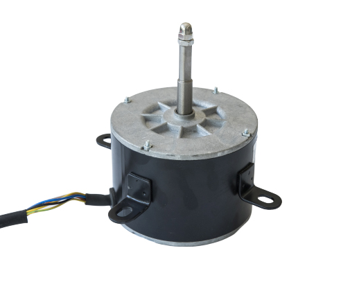
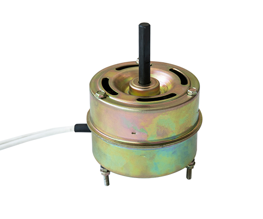
AC asynchronous motors are motors that run on AC voltage. They are widely used in electric fans, refrigerators, washing machines, air conditioners, hair dryers, vacuum cleaners, range hoods, dishwashers, electric sewing machines, food processing machines and other household appliances and various electric appliances. Tools, small electromechanical equipment.
AC asynchronous motors are divided into induction motors and AC commutator motors. Induction motors are divided into single-phase asynchronous motors, AC and DC dual-purpose motors and repulsion motors.
1. Single-phase asynchronous motor Single-phase asynchronous motor consists of stator, rotor, bearing, casing, end cover and so on.
The stator consists of a base and an iron core with windings. The core is made of silicon steel sheet punched and laminated, and two sets of main windings (also called running windings) and auxiliary windings (also called starting windings into secondary windings) with a distance of 900 electrical degrees are embedded in the slots. The main winding is connected to the AC power supply, and the auxiliary winding is connected to the centrifugal switch S or the starting capacitor and the running capacitor in series, and then the power supply is connected.
The rotor is a cage-type cast aluminum rotor. The core is laminated with aluminum and cast into the groove of the core, and the end rings are cast together to short-circuit the rotor bar into a squirrel cage.
Single-phase asynchronous motors are divided into single-phase resistance-start asynchronous motors, single-phase capacitor-start asynchronous motors, single-phase capacitor-running asynchronous motors, and single-phase dual-value capacitor asynchronous motors. Figure 18-14 shows the electrical principles of several single-phase asynchronous motors. line.
2. Three-phase asynchronous motor The structure of a three-phase asynchronous motor is similar to that of a single-phase asynchronous motor. Three-phase windings are embedded in the stator core slots (there are three structures of single-layer chain type, single-layer concentric type and single-layer cross type). After the stator winding is connected to a three-phase AC power supply, the rotating magnetic field generated by the winding current generates an induced current in the rotor conductor. The rotor generates an electromagnetic rotary cabinet (ie asynchronous rotary cabinet) under the interaction of the induced current and the air gap rotating magnetic field. , Make the motor rotate.
3. Shaded pole motor The shaded pole motor is the simplest one of the one-way AC motors, usually using a cage-shaped skew-slot cast aluminum rotor. It is divided into salient pole shaded pole motor, hidden pole shaded pole motor according to the different shape and structure of the stator.
The shape of the stator core of the salient-pole shaded pole motor is a square, rectangular or circular magnetic field frame with protruding magnetic poles. Each magnetic pole has one or more auxiliary short-circuit copper rings, namely shaded pole windings. The concentrated winding on the salient poles serves as the main winding.
The stator core of the hidden pole shaded pole motor is the same as that of the ordinary single-phase motor. Its stator winding adopts distributed winding, and the main winding is distributed in the stator slot. The shaded pole winding does not need to short-circuit the copper ring, but is wound with thicker enameled wire Distributed windings (short-circuit after being connected in series) are embedded in the stator slots (approximately 1/3 of the total number of slots), acting as an auxiliary group. The main winding and the shaded pole winding are spaced at a certain angle.
When the main winding of the shaded pole motor is energized, the shaded pole winding will also generate an induced current, which causes the magnetic flux of the part of the stator pole covered by the shaded pole winding and the uncovered part to rotate in the direction of the covered part.
34. Single-phase series-excited motor The stator of a single-phase series-excited motor is composed of a salient pole core and an excitation winding, and the rotor is composed of a salient pole core, armature winding, commutator, and rotating shaft. A series circuit is formed between the field winding and the armature winding through the brush and the commutator. Figure 18-16 shows the structure of a unidirectional series motor.
The single-phase series motor is an AC and DC dual-purpose motor. It can work with AC power supply or DC power supply.
(4) AC synchronous motor
AC synchronous motor is a constant-speed drive motor whose rotor speed maintains a constant proportional relationship with the power frequency. It is widely used in electronic instrumentation, modern office equipment, textile machinery, etc.
1. Permanent magnet synchronous motor Permanent magnet synchronous motor belongs to asynchronous start permanent magnet synchronous motor. Its magnetic field system is composed of one or more permanent magnets, usually inside the cage rotor welded with cast aluminum or copper bars, as required The number of poles is equipped with magnetic poles inlaid with permanent magnets. The stator structure is similar to that of an asynchronous motor.
When the stator winding is connected to the power supply, the motor starts and rotates according to the principle of asynchronous motor, and when it accelerates to a synchronous speed, the synchronous electromagnetic torque generated by the permanent magnetic field of the rotor and the stator magnetic field (the electromagnetic torque generated by the permanent magnetic field of the rotor is compared with The reluctance torque synthesis produced by the stator magnetic field pulls the rotor into synchronization, and the motor enters synchronous operation.
Reluctance Synchronous Motor Reluctance synchronous motor, also called reactive synchronous motor, is a synchronous motor that generates reluctance torque by using the rotor quadrature axis and direct axis reluctance to generate reluctance torque. Its stator has a similar structure to that of an asynchronous motor, except for the rotor structure. different.
The reluctance synchronous motor is evolved from the cage-type asynchronous motor. In order to make the motor generate asynchronous starting torque, the rotor is also equipped with a cage-type cast aluminum winding. The rotor is provided with reaction slots corresponding to the number of stator poles (only the role of salient poles, no excitation windings and permanent magnets), which are used to generate reluctance synchronous torque. According to the structure of the reaction tank on the rotor, it can be divided into an inner reaction type rotor, an outer reaction type rotor and an inner and outer reaction type rotor. Among them, the outer reaction type rotor has the reaction groove open on the outer circle of the rotor to make its straight axis and quadrature axis direction. The air gap varies. The inner reaction type rotor has grooves inside, so that the magnetic flux in the quadrature axis direction is blocked, and the magnetic resistance is increased. The internal and external reactive rotors combine the structural characteristics of the above two types of rotors, and the difference between the straight shaft and the quadrature shaft is large, so that the power of the motor is greater. Reluctance synchronous motors are also divided into single-phase capacitor operation type, single-phase capacitor starting type, single-phase dual-value capacitor type and many other types.
3. Hysteresis synchronous motor Hysteresis synchronous motor is a synchronous motor that uses hysteresis materials to generate hysteresis torque and work. It is divided into inner rotor type hysteresis synchronous motor, outer rotor type hysteresis synchronous motor and single-phase shaded pole type hysteresis synchronous motor.
The rotor structure of the inner rotor type hysteresis synchronous motor is a hidden pole type, and the appearance is a smooth cylinder. There is no winding on the rotor, but there is a ring-shaped effective layer made of hysteresis material on the outer circle of the iron core.
After the stator winding is connected to the power supply, the generated rotating magnetic field causes the hysteresis rotor to generate asynchronous torque to start the rotation, and then it will automatically enter the synchronous operation state. When the motor is running asynchronously, the stator rotating magnetic field repeatedly magnetizes the rotor at the slip frequency; when running synchronously, the hysteresis material on the rotor is magnetized and permanent magnetic poles appear, thereby generating synchronous torque.
 English
 简体中文
简体中文 عربي
عربي